DIY Retractable Caster Wheels: Lift & Lock Build
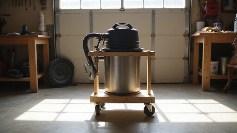
If you’re tired of moving a heavy workbench around or want it to stay rock solid during use, retractable caster wheels might be just what you need. These clever wheels lift the workbench off the floor and lock in place, giving you stability when you work and mobility when you want it.
You’ll learn how to build a simple yet effective lift and lock system using just a few parts.
By the end, you’ll be able to create a setup that keeps your workspace steady and easily movable. Everything you need to get started is right here.
Why Retractable Casters Fix Workbench Stability
Retractable casters improve workbench stability by allowing your bench to rest directly on its legs or feet when parked. This means the wheels are disengaged, providing a rigid contact with the floor instead of relying on pivoting wheels. Eliminating wheel flex, swivel play, and minor wobbling results in a more stable setup. When selecting components, consider top furniture sliders for carpet to protect flooring during assembly.
This stability is especially noticeable when you’re planing, chiseling, or working with delicate surfaces. Reduced vibration minimizes chatter and makes for cleaner, more precise work. On uneven floors, you can adjust each support point to prevent rocking, so your work remains steady regardless of surface irregularities. A similar principle drives the design of collapsible folding wagons, where retracted wheels ensure a solid base for heavy loads.
Switching between move mode and work mode becomes effortless, as your bench remains firmly planted during operation. The load capacity is preserved, since all the weight is supported by the structure itself with the casters retracted, not the wheels. Additionally, maintenance is easier—since the hardware disengages during work, it avoids constant pressure and wear on the casters. For a similar budget-friendly no-weld build that skips specialist tools, many DIYers adapt these principles to a simple wheeled dolly design.
Choose Your Caster Design: Parallelogram vs. Lead Screw vs. Over-Center
Choosing between parallelogram, lead screw, and over-center caster mechanisms depends on your specific needs and constraints. Parallelogram setups provide smooth, parallel wheel motion, which helps in maintaining alignment during movement. However, they require precise material selection and multiple pivot points, making them more complex to build. Longer lever arms can reduce the force needed for movement but demand additional clearance space. Lead screw systems are prized for their precision, allowing fine height adjustments with typically self-locking capabilities. This makes them ideal if you need controlled lifting or positioning. But they generally involve slower movement and can create more friction, requiring regular maintenance or lubrication. A cam action under the wheels lifts the weight effectively when the lead screw rotates. Over-center mechanisms lock into position with a positive snap, holding the caster securely without continuous input. This design simplifies operation and improves stability but may produce higher actuation forces during engagement. Correct geometric tuning is critical to ensure they lock reliably and resist accidental collapse. Before finalizing any mount, verify that your safety check process confirms all pivot bolts are torqued to spec and that moving parts clear the truck bed’s tailgate latch, similar to how a bed extender’s installation ends with a structural inspection. For inspiration on stable hauling designs, consider how bike trailer frames use reinforced struts to manage load distribution during transport. A similar low-cost approach can be applied by using DIY bungee cords to secure components temporarily during assembly, eliminating the need for welding or special tools.
Gather the Parts: Wheels, Pivots, Brackets, and Linkage Arms
Gather the parts: Wheels, pivots, brackets, and linkage arms before you start cutting or welding. Select wheels made from steel, polyurethane, or cast iron based on the weight your setup will bear and the floor type—material compatibility is essential for durability. Side-mount or carrier-style wheels simplify the design of retractable systems. Use a bolt, nut, and bearing stack to ensure smooth and reliable rotation. For securing the equipment during transport, consider the same principles used in the best ratchet straps for mattress to hold loads firmly in place. For those hauling gear in a truck bed, a bed extender can help secure longer items during transit. When outfitting a wagon with such a system, consider using UV-resistant canopy fabric to protect both the hardware and any cargo from sun damage during extended outdoor use.
Choose pivot brackets that prevent binding; their positioning determines your over-center lock action. Steel plate brackets are common and often come with pre-drilled patterns, making mounting easier. Linkage arms transfer your input force to lift or move the wheel. Typically, a lower and upper lever work in tandem, with a heel on the locking lever to hold the position under load. Ensure the linkage moves the wheel from full floor contact to a nearly lifted position with minimal force, matching wheel size and load rating to your equipment’s total weight.
Measure Frame-to-Floor Clearance for Proper Lift Height
To measure frame-to-floor clearance accurately, start by identifying the lowest fixed point on your frame, including protruding fasteners, weld beads, or linkage hardware. Measure from this point straight down to the floor, ensuring you do not use a flat, convenient section but the smallest gap available. Irregularities like thresholds or debris can artificially increase the gap, so always include a safety margin to prevent your design from binding during operation. Take multiple measurements in the frame’s normal loaded position, as frames often flex under load. The smallest reading across these measurements becomes your critical clearance figure. For low-clearance setups, aim for a total base height between 3.25 inches and 4.5 inches. Match your caster height to this gap—not the other way around—to ensure proper lift height and mobility. Remember, measurement accuracy is key; a perfect fit on a flat workbench may not suit a real-world floor with imperfections. Always account for wheel radius, bracket thickness, and linkage travel within your clearance budget before cutting any metal to avoid surprises during assembly. Reviewing top utility carts with wheels can help you identify ideal caster height combinations for your specific floor conditions. For additional guidance, compare your selected caster dimensions against garden cart reviews that specify wheel sizes for similar load capacities. When matching your setup to wheelbarrow-style loads, consider that best pneumatic tires often provide superior shock absorption on uneven terrain.
Build and Assemble Your Retractable Caster Linkage
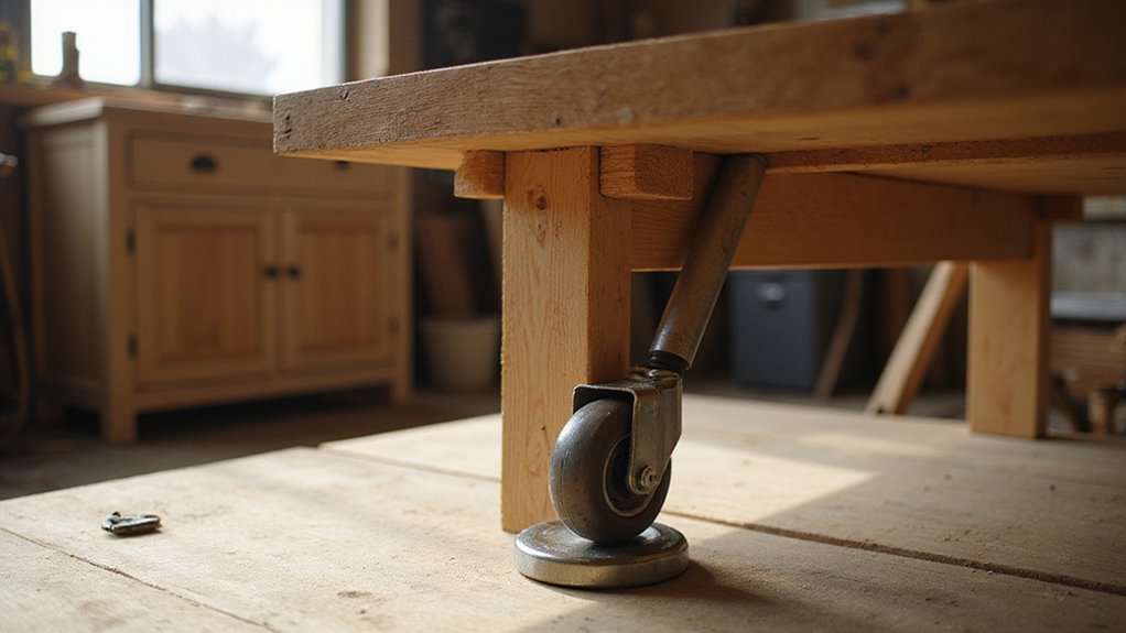
To build the retractable caster linkage, start by accurately measuring your frame-to-floor clearance. This measurement determines the length of your square-tubing carrier body. Use steel square tubing for the carrier and matching plates for the caster mounts. Lay out the carrier body as a square tube and attach side-mount carrier plates for each leg, ensuring they are aligned properly. Adopt a pulling method for force translation, as it offers superior stiffness and cost-effectiveness for the linkage. This approach also helps reduce overall material costs when building your own golf push cart. This design functions as a second-class lever, giving you the mechanical advantage to lift heavy loads with minimal effort. Understanding your yard’s volume in cubic yards can help you estimate how much concrete or dirt you will need to move with your cart.
Next, drill two pivot holes in each carrier plate: one for the caster arm, positioned closer to the leg, and another for the locking lever, located farther out. Use a 1/4-inch bolt through a drilled coupler nut for the pivot hardware—this prevents metal-to-metal contact and allows smooth rotation. Weld the coupler nut onto the caster plate securely, then test-fit the assembled linkage before completing final welding.
The locking lever should have a heel extending past its pivot toward the caster. Mock it up from rectangular tubing to ensure proper fit and movement. Clamp the carrier to your leg, align everything precisely, and drill four mounting holes to bolt the assembly securely in place. Avoid rushing to ensure the linkage functions smoothly and is sturdy enough for repeated use.
Fix Common Mistakes That Cause Binding or Instability
To fix binding or instability in your retractable caster setup, first check for common mounting and alignment errors. An uneven mount or misaligned wheel path causes lateral forces that lead to flutter, so perform alignment correction immediately. Tighten all fasteners and ensure the mounting plate sits flush against the surface. If the mechanism still binds, inspect for debris or damaged bearings—dirt and grit can jam the swivel path and hinder movement. For long-term prevention, regularly clean caster wheels to remove buildup that can seize the swivel mechanism. For additional insight on reducing friction, refer to easy tips for using your bicycle rear rack efficiently to apply similar load-balancing principles. Regular lubrication of moving parts is essential to prevent sticking and maintain smooth operation. Also, examine the load distribution across all casters; overloading one caster increases wobble and strains the lift system. Worn wheels or bent brackets should be replaced, as they are frequent causes of recurring instability. Finally, replace damaged bearings to ensure the swivel rotates freely without binding. Lastly, verify that your casters are suited to your floor type and operating speed. Mismatched components or exceeding recommended speeds can cause uneven wear and impair stability. Addressing these issues systematically will eliminate binding and improve your caster performance.